Exoskeleton Control
The current method of providing assistance to a stroke patient learning to walk again involves having a patient partially suspended on an elevated treadmill and the physical therapist manually manipulates the patient’s legs one at a time to help patient improve the patient’s gait pattern. An improvement on this method would be to use a lower body exoskeleton that would be able to control each joint on the patient individually. Work has been done by Emek Barış Küçüktabak on creating a system where both users wear an exoskeleton and are virtually coupled to allow both users to affect each other’s gait pattern. Starting from where Emek left off, I aimed to remove one of the exoskeletons from the setup to make physical therapy sessions requiring an exoskeleton more efficient.
Video demonstration of the physical therapist controlling an exoskeleton I am wearing
This demo demonstrates the physical therapist on the right using Inertial Measurement Units (IMU) and sensors attached to her legs controlling the lower body exoskeleton I am wearing on the left.
Sensors
The sensors used for this project are the Trigno combination IMU and EMG sensors that are placed on the legs. As shown below, the color coding highlights the purpose of each sensor. IMU sensors record the movement and rotation of the sensor, meaning if I fix an IMU to a user’s leg, I can read the current angle of the user’s hip and knee joints.
The sensors are placed on the legs in the following locations.
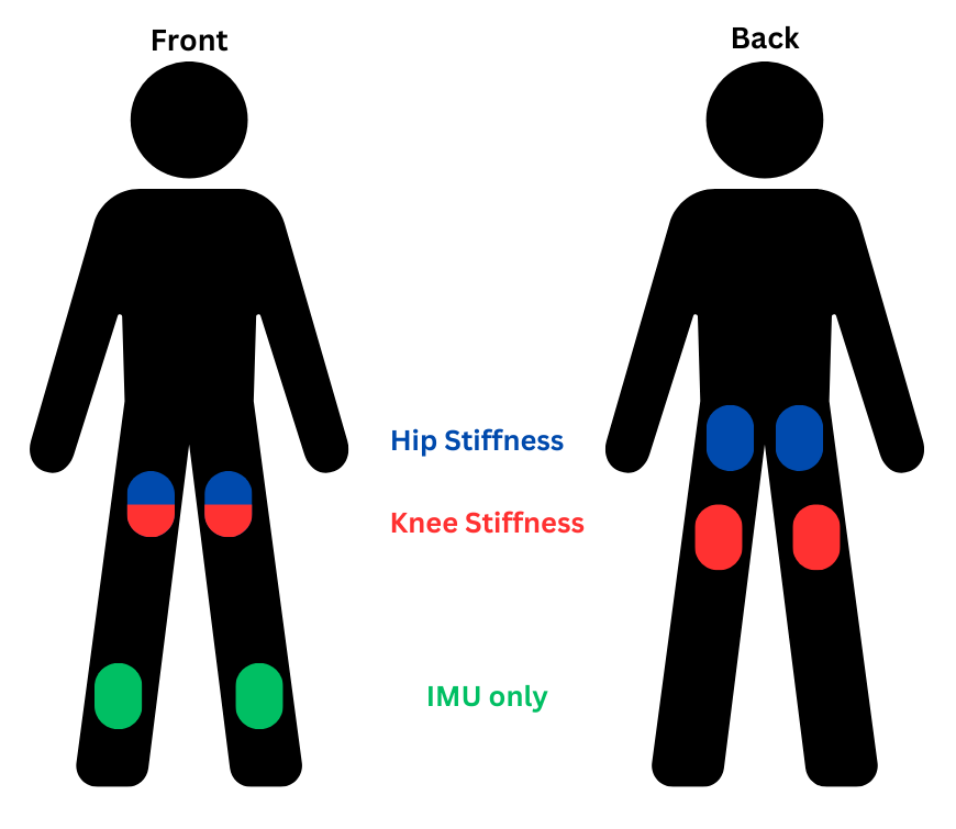
Muscle activation:
- EMG data is collected from the quadriceps and the gluteus maximus (Blue sensors)
- EMG data is collected from the quadriceps hamstrings (Red sensors)
Desired position of the joints:
- IMU data is collected from the quadriceps hamstrings (Red sensors)
- Only IMU data is collected from the sensors on the shin (Green sensors)
IMU controller
The first step in this project was getting IMU sensors on the different segments on a person’s legs to control the exoskeleton using a position controller.
Video demonstration of me controlling a simulated exo skeleton using the IMU sensors on my legs
The video above shows me controlling a simulated exoskeleton using the IMU Trigno sensors on my legs. A simulated exoskeleton was used for ease of viewing.
The quaternions that the IMUs generate are converted into joint angles in the sagittal plane of the therapist’s body. Those joint angles are then fed to a position controller that commands motor torques based on the difference between the joint angles of the therapist and the joint angles of the exoskeleton.
This method allows the physical therapist to easily command a desired gait pattern to a patient while enabling the therapist to easily put on and take off the sensors to attend to other tasks during a therapy session.
EMG stiffness augmentation
An important part of lower body rehabilitation using this setup is being able to vary controller stiffness to encourage the patient to tend towards more desirable gait patterns as the physical therapist sees fit. During test using only the IMUs controlling the desired position, an operator would control the proportional gain on the controller, changing it when the therapist said to do so. This method is functional but is more cumbersome and is less likely to find the correct stiffness. Also, different phases of a patient’s gait pattern could require different levels of stiffness. This is why I aimed to augment the controller’s proportional stiffness based on the muscle activation of the therapist wearing the IMU/EMG sensors.

The graphs above show the EMG to stiffness pipeline. The first graph shows EMG readings as they are received from the sensors in millivolts. Then they are converted into muscle activation percentages for each muscle based on individual user calibration values obtained during a calibration process. From there the muscle activation values for antagonist muscles are combined using the selected stiffness calculation method to determine the stiffness value for that joint. In the case above, the muscles on the front and back of the thigh control the flexion and extension of the knee joint so those muscle activation values are used to calculate knee stiffness.
- High-Low method:

Where σ is an array containing maximum voluntary contraction (MVC) readings for both muscles that control that joint
- Maximum method:
Takes the maximum of the two MVC readings and converts that directly to the stiffness multiplier for the controller.
- Minimum method:
Takes the minimum of the two MVC readings and converts that directly to the stiffness multiplier for the controller.
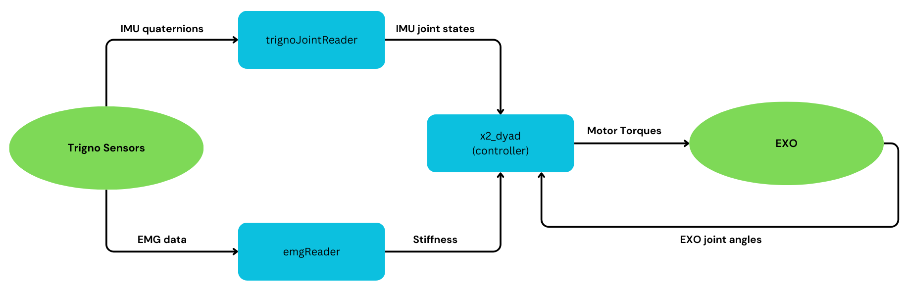
The final flowchart showing the ROS nodes and data flow is as follows:
Future work
This project has the opportunity to be improved on in the future, as the goal was to create an intuitive and easily controllable system for rehabilitation therapy, other methods for calculating stiffness could be more intuitive.
Forearm contraction method
One method that I did not have the time to experiment with was using the contraction of another part of the body, such as the forearm, to augment joint stiffness. During my experiments I found it can be difficult to flex parts of the leg enough to significantly change the perceived muscle activation without significantly changing the kinematics of my gait. Using the muscle activation of another muscle not on the leg would be a creative way to avoid this issue.
Percent of maximum output torque
The current method of figuring out the amount that the user is contracting their muscles does not take into account the strength of each muscle relative to the other antagonist muscles. Using some calibration method that takes into account each muscle’s strength would make a more accurate controller as relative stengths would be able to be used when calculating stiffness.
References: [1] E. Küçüktabak, Y. Wen, M. Short, E. Demirbaş, K. Lynch, and J. Pons, “Virtual Physical Coupling of Two Lower-Limb Exoskeletons.” [Online]. Available: https://arxiv.org/pdf/2307.06479